 SKU: DAT-ST-711
Model: ST-711
Manufactured by: Datel/Intersil
The A/D section on the ST-711 uses Datel’s hybrid technology ADC-HS12B combined successive approximation A/D converter and sample/hold amplifier. The ADC-HS leatures 6 uses S/H acquisition time and B uses A/D conversion time and 12 bit binary resolution (1 part in 4096). System accuracy varies from =0.05% of FSR =1/2 LSB (10 volt range) to =0.3% FSR =1/2 LSB (10 mV range), including noise, quantization, nonlinearity and dynamic errors. The ST-711 employs Datel's MX-1606 series fast CMOS multiplexers which incorporate =35V over voltage protection. Input impedance is 100 megohms minimum (power on) with 30 pA typical input bias current. Balanced inputs require 5 kilohms maximum source impedance to maintain accuracy and throughput rate. All models include an FET input differential amplifier which is wired as single-ended for the 32 channel models. This diff. Amp. will accept a fixed resistor to increase the gain to 1000, making 10 millivolts full scale ranges practical. For differential inputs, the common mode voltage is =12V to analog common. Common mode noise rejection varies from 120dB at dc with a gain of 8 to 60 dB at 60 Hz with a gain of 1000 Sample/Hold aperture delay time is 100 nanoseconds, maximum.
System temperature coefficients are =25 ppm of FSA/oC (gain drift of gain *1) and =20uV/oC (RT1) zero drift. Amplifier setting time is 6 microseconds (high level) and typically 110 microseconds (low level). Overall system throughout rate for high level signals is 23,000 samples per second.
The standard A/D- D/A digital coding is off-set binary (bipolar) but jumpers may easily be changed to straight binary (unipolar) or 2’s complement (bipolar). Standard A/D-D/A analog signal ranges are =10V full scale but may be jumper selected to =5V, or +5V or + 10V unipolar.
D/A outputs include op amps for voltage outputs, giving very low output impedance (2/10’s of an ohm) at mA short circuit proof output current. D/A setting time is 4 uS(ES pk-pk change). Output temperature drift is a 50 ppm lo FSR/oC 4 to 20 mA current loop outputs accept a 15 to 30 Vdc voltage compliance with =0.075% FSR accuracy and =50 ppm FSR/oC drift.
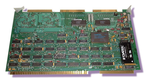
Click on thumbnail for larger image. Call for price.
|
|||
|
|
Multibus-International |
|
|
|