 SKU: INT-SBC508
Model: SBC508
Manufactured by: Intel Corporation
The Input/Output (I/O) Expansion Board has been designed to increase the I/O capacity of any SBC80 Single Board Computer. The I/O Expansion Board can also be used as part of the INTELLEC MDS Microcomputer Development System.
The I/O Expansion Board includes four input and four output ports. Each output port latches 8-bit data words and issues a framed strobe pulse, of selectable duration, to the device. All outputs are driven by TTL level buffer drivers. Each input port also supports 8 bits of data, latched or unlatched. All inputs are terminated by dual-in-line, socket-mounted resistor packs.
The I/O Board includes provisions for accepting eight external interrupt requests, buffering them and driving them on eight interrupt priority level lines. In addition, each of the eight I/O ports includes an interrupt request line that is activated by a strobe pulse from the device, then automatically cleared after the port is serviced. These port interrupt requests can be asserted on the system interrupt priority lines or can be used to feed an interrupt status port on this or another module, WHEN USED IN CONJUNCTION WITH THE SBC80/10, ONLY ONE INTERRUPT REQUEST LINE IS USED.
The I/O Board accepts eight address inputs from the CPU. The two least significant address bits select one of the four input or output ports, while the six high-order address bits select the I/O Board. That is, these six high-order bits specify the BASE address of the I/O Board to be accessed. The user can select any one of 64 unique values for the BASE address (switch-selectable).
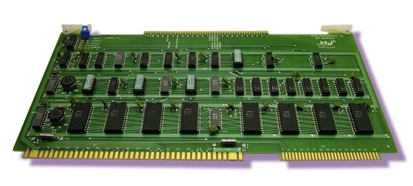
The I/O Board is implemented on a single, 12-in x 6.75-in. printed circuit board. The board requires only +5 VDC power. Power and all system signals enter the board through an 86-pin, double sided edge connector. An auxiliary 60-pin connector is available for use as a means of reaching various test points. The module communicates with all peripheral devices via a 100-pin, double-sided edge connector, located on the top of the module, opposite the 86- and 60-pin connectors.
Click on thumbnail for larger image. Call for price.
|
|||
|
|
Multibus-International |
|
|
|